How To Make A Mobile/Cellphone Signal Booster Using LM386 Op-Amp IC

What is a Mobile/Cellphone Signal Booster?
A mobile/cellphone signal booster is basically a repeater system that allows an amplifier to add gain or power to the phone's reception signal in different directions. Its main aim is to take in an existing cellular signal around your car, office, workstation, or home and then rebroadcast a boosted signal, after passing it through an amplifier. One important thing to take into consideration is that a cell phone signal booster is designed to work with an already existing and stable transmission. If there is an existing transmission, only then a mobile signal booster will be able to amplify and transmit the cellular carrier's signal. So, in today's tutorial, we are going to go over a step by step process on How To Make A Mobile/Cellphone Signal Booster Using the LM386 Op-Amp IC.
[post_start1]Any Cellular signal boosting system comprises of three key elements. An external antenna, an operational amplifier, and an interior antenna. Together, these essential elements form a wireless system to boost mobile reception. Basically, almost every signal amplifier today is an analog one, meaning that they amplify all mobile phone carrier frequencies using traditional technology.
LM386
LM386 is a low power audio frequency amplifier IC that is commonly used in small scale audio amplifiers. The IC requires a small amount of power to operate & hence can easily be used with a 9V battery. The gain of LM386 IC is internally set to 20 to keep the external part count low, but the addition of an external resistor and capacitor between pins 1 and 8 will increase the gain to any value from 20 to 200.
[post_start1]
Hardware Components
You will need the following parts to build this project:
| S.No | Component | Value | Qty |
|---|---|---|---|
| 1) | Op-Amp IC | LM386 | 1 |
| 2) | Enameled Copper Wire | 22 AWG | 1 meter |
| 3) | Capacitor | 4700uF/10V, 1000uF, 10uF | 3 |
| 4) | Resistor | 1K | 1 |
| 5) | Soldering Iron | 45W - 65W | 1 |
| 6) | Soldering wire with flux | - | 1 |
| 7) | DC Battery | 5V - 9V | 1 |
| 8) | Battery Clip | - | 1 |
| 9) | Veroboard | - | 1 |
| 10) | Smartphone/Mobile phone | - | 1 |
| 11) | Jumper Wires | - | As per need |
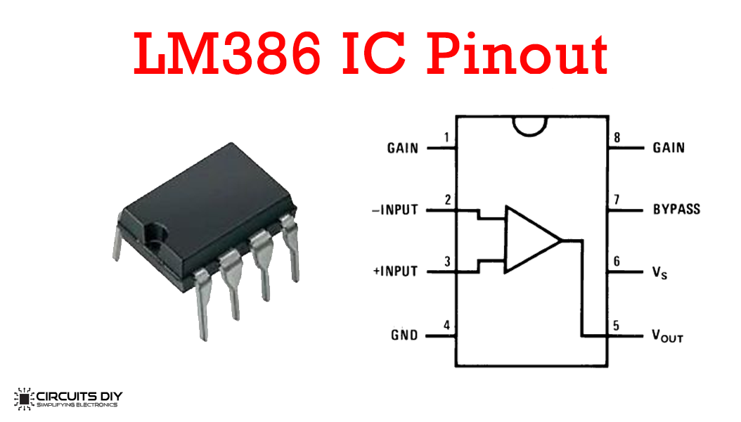
LM386 Pinout
Useful Steps
1) Solder the LM386 Op-Amp on the veroboard.

2) After that, Solder the 1K resistor between pin 3 and 2 of the IC.


4) After that, solder the -ve pin of the 4700uF capacitor with pin 4 & the +ve pin with pin 4 of the IC.

5) Now, solder the +ve terminal of the 1000uF capacitor with pin 5 of the Op-amp IC and the -ve terminal with the output aerial antenna.

6) Coil 2 pieces of enameled copper wire to make I/O antennas (Keep the length of the output aerial antenna greater than that of the input). After that, solder the input aerial antenna with pin 3 of the IC and the output antenna with pin no.5, at the 1000uF capacitors -ve pin.

7) Connect the +ve pin of the battery clip with pin 6 of the IC and -ve with pin no.4 of the IC.

8) Power up and test the circuit.

Working Explanation
The working of this circuit is as follows. On powering on the circuit, the input antenna starts to capture the weak transmission surrounding the cellphone/mobile. As a result, the captured transmission is transferred to the non - inverting input of the LM38658 Op-amp. The LM358 op-amp conditions and amplifies the input signal, while maintaining the same address and mapping as that of the input transmission.
[post_start1]The amplified output from the LM386 op-amp then passes through a filtering capacitor, in order to remove any residual noise from the amplifier output. After that, the strengthened capacitor output is then rebroadcasted and is now picked by the cellular device.
Applications
- Mobile phone signal boosters are used to boost 4G LTE, 3G, or 2G voice signals in places such as your car or home.
- Also used to enhance internet speed, text, and talk quality. Also to maintain a reliable connection throughput at all times.
- Used to widen cellular reception areas in mountainous regions.
See Also: How To Make An FM Radio Receiver Using LM386 Audio Amplifier IC | DIY | Power Inverter (200W) Using CD4047 Monostable/Astable Multivibrator IC | How To Make An Audio Power Amplifier Using TDA2003 Amplifier IC
Comments 0
Be the first to comment.
Leave a comment