

What is an Anti-Theft Wallet Security Alarm?
People always think that it will never happen to them until it does. One minute your wallet is securely in your pocket and the next minute, you are frantically trying to search for it. Wallet theft is a disease that plagues our community, costing people hundreds financially or worse, thousands if the thief realizes the value of your credit cards & personal ID, and has the means & will to sell them to the highest bidder. Anti-Theft Wallet Security Alarm is a simple security measure, that you can take to ensure that your valuables are safe from the prying eyes of thieves and robbers.
There are many variations of anti-theft wallets available in today’s market, usually fitted with RFID tags to keep your wallet safe. But they tend to be quite expensive and usually require you to move all the contents of your previous wallet into a new one. So, in this tutorial we are going to design a cheap and simple Anti-Theft Wallet Security Alarm Circuit Using an LDR & a transistor.
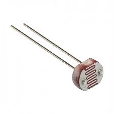
LDR (Light Dependent Resistor)
LDRs are electronic components that are sensitive to light intensity. Its behavior is similar to a photocell that works on the principle of photoconductivity. This passive component is basically a resistor whose resistance value decreases when the intensity of light increases. It is not uncommon for the values of resistance of an LDR or photoresistor to be at several MΩ in darkness and then to fall to a few hundred ohms in bright light.
Hardware Components
You will need the following parts to build this project:
| S.No | Component | Value | Qty |
|---|---|---|---|
| 1) | LDR | 5mm | 1 |
| 2) | Transistor | BC547, NPN | 1 |
| 3) | Resistor | 1K, 220 Ohm | 2 |
| 4) | Buzzer | 5V | 1 |
| 5) | Soldering Iron | 45W – 65W | 1 |
| 6) | Soldering Wire with Flux | – | 1 |
| 7) | Veroboard | – | 1 |
| 8) | DC Battery | 9V | 1 |
| 9) | Battery Clip | – | 1 |
| 10) | Jumper Wires | – | As per need |
BC547 Pinout
LDR
Useful Steps
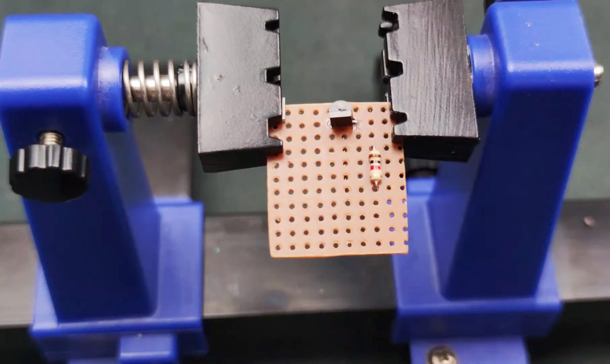
1) Solder the BC547 transistor on the Veroboard.

2) After that, solder a 1K resistor between the emitter and base terminal of the BC547 transistor.
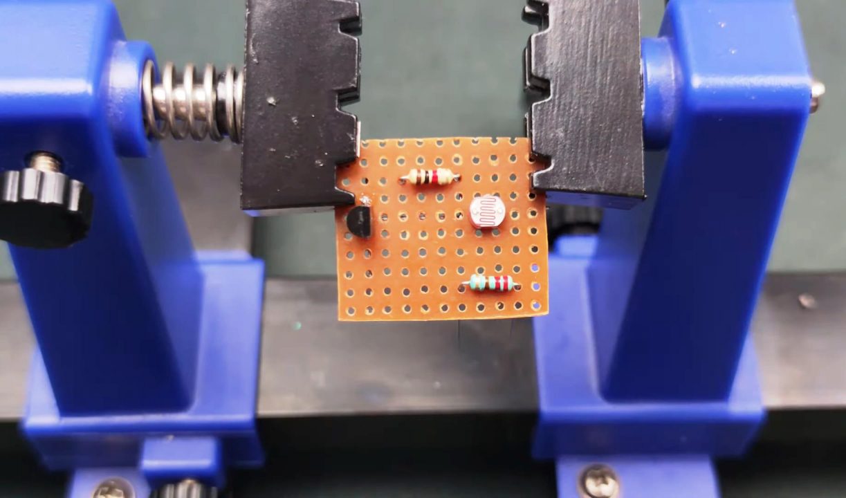
4) After that, solder a 220 Ohm resistor between the -ve terminal of the buzzer & the LDR. Also, solder the -ve terminal of the buzzer with the collector terminal of the BC547 transistor.
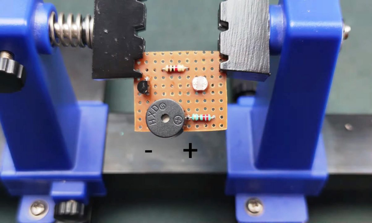
5) Solder a +veand -ve pins of the battery clip with the +ve terminal of the buzzer and emitter pin of the transistor respectively.
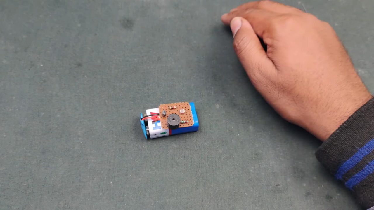
6) Power up & test the circuit.
Working Explanation
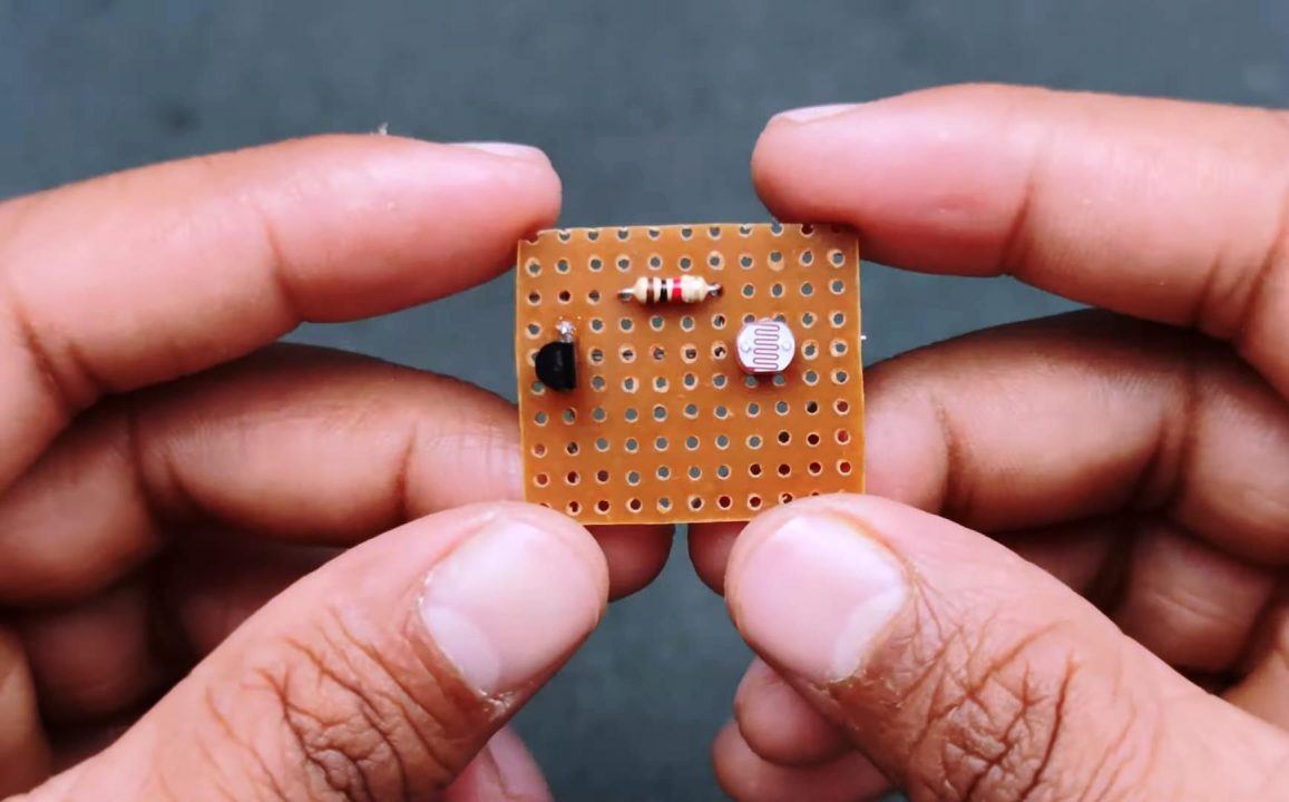
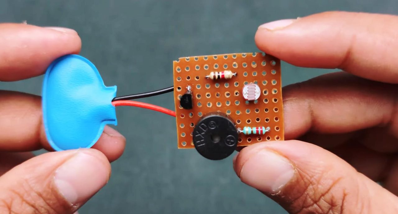
The working of this circuit is actually pretty simple. In order to effectively use this circuit, you make it on small Veroboard while keeping the components in a compact layout. This will allow you to easily fit this circuit in your wallet or a purse. Also, make sure that the LDR is always pointing outwards whenever you or someone else is opening the wallet.
When someone opens the wallet, the LDR is exposed to daylight, allowing it’s resistance to rise rapidly. This increases the intensity of the control signal on the base of the BC547 transistor. The collector output from the transistor triggers the buzzer to go off, alerting you immediately if someone is trying to gain access to your wallet without permission. Similarly, when the wallet is closed, the light intensity on the surface of the LDR reduces, decreasing its resistance. This subsequently diminishes the intensity of the control signal on the base of the transistor and the buzzer turns off,
Applications
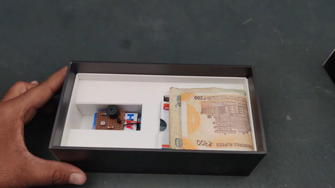
- It is commonly used to protect valuables such as wallets, purses, safes, etc.
- It is also used to alert you in case someone is try to gain access to you valuables without permission.
See Also: How To Interface MQ2 Gas Sensor With Arduino Uno | DIY Arduino Project | Simple Voltage Level Indicator Using LM3914 Dot/Bar Display Driver | DIY | H-Bridge Motor Controller Using Power Transistors

