How To Make An FM Radio Receiver Using LM386 Audio Amplifier IC | DIY
What is an FM Radio Receiver?
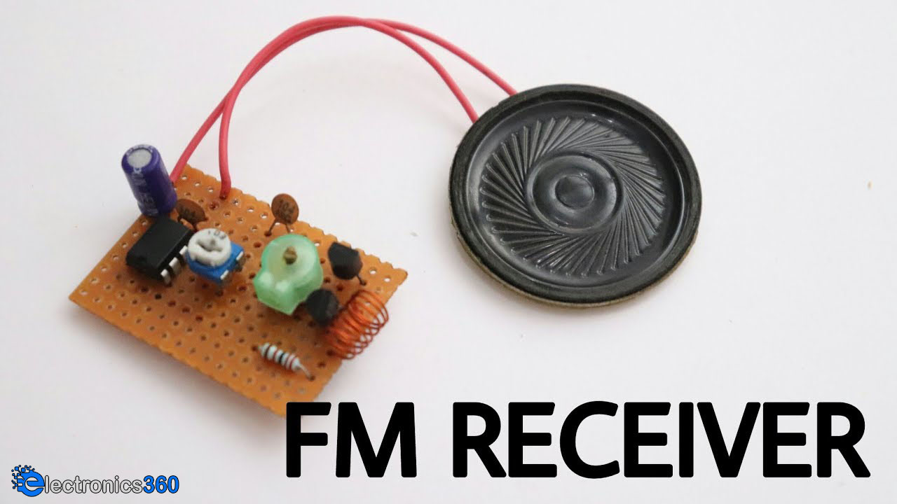
An FM radio receiver is an electronic configuration that takes in FM radio waves and converts them into an audible form. Basically, It takes the modulated FM signal as an input and outputs the original audio signal to an audio transducer such as a loudspeaker. FM radio receivers are mainly utilized for radio communication and can be seen in devices such as Ham radios, Portable Walkie Talkies, and MP3 Players, etc. So, In today's tutorial, we are going to go over a step by step procedure on How To Make An FM Radio Receiver Using LM386 Audio Amplifier IC.
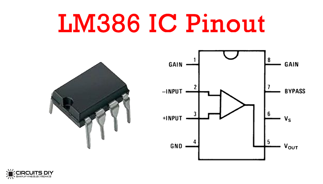
[post_start1]The heart of this circuit is an LM386 IC. LM386 is a low power audio frequency amplifier IC that is commonly used in small scale audio amplifiers. The IC requires a small amount of power to operate & hence can easily be used with a 9V battery. The gain of LM386 IC is internally set to 20 to keep the external part count low, but the addition of an external resistor and capacitor between pins 1 and 8 will increase the gain to any value from 20 to 200.
Hardware Components
You will need the following parts to build this project:
| S.No | Component | Value | Qty |
|---|---|---|---|
| 1) | Audio Amplifier IC | LM386 | 1 |
| 2) | NPN transistor | BF494 | 2 |
| 3) | Enameled Copper Wire | 7 Turns, 27 AWG, 1mH | 1/2 meter |
| 4) | Loudspeaker | 4 Ohms | 1 |
| 5) | Trimmer Capacitor | 22pF | 1 |
| 6) | Capacitor | 100nF, 100uF | 3 |
| 7) | Resistor | 22K | 1 |
| 8) | Potentiometer | 10K | 1 |
| 9) | Soldering Iron | 45W - 65W | 1 |
| 10) | Soldering Wire with Flux | - | 1 |
| 11) | DC Battery with clip | 12V | 1 |
| 12) | Veroboard | - | 1 |
| 13) | Jumper Wires | - | As per need |
LM386 Pinout
Useful Steps
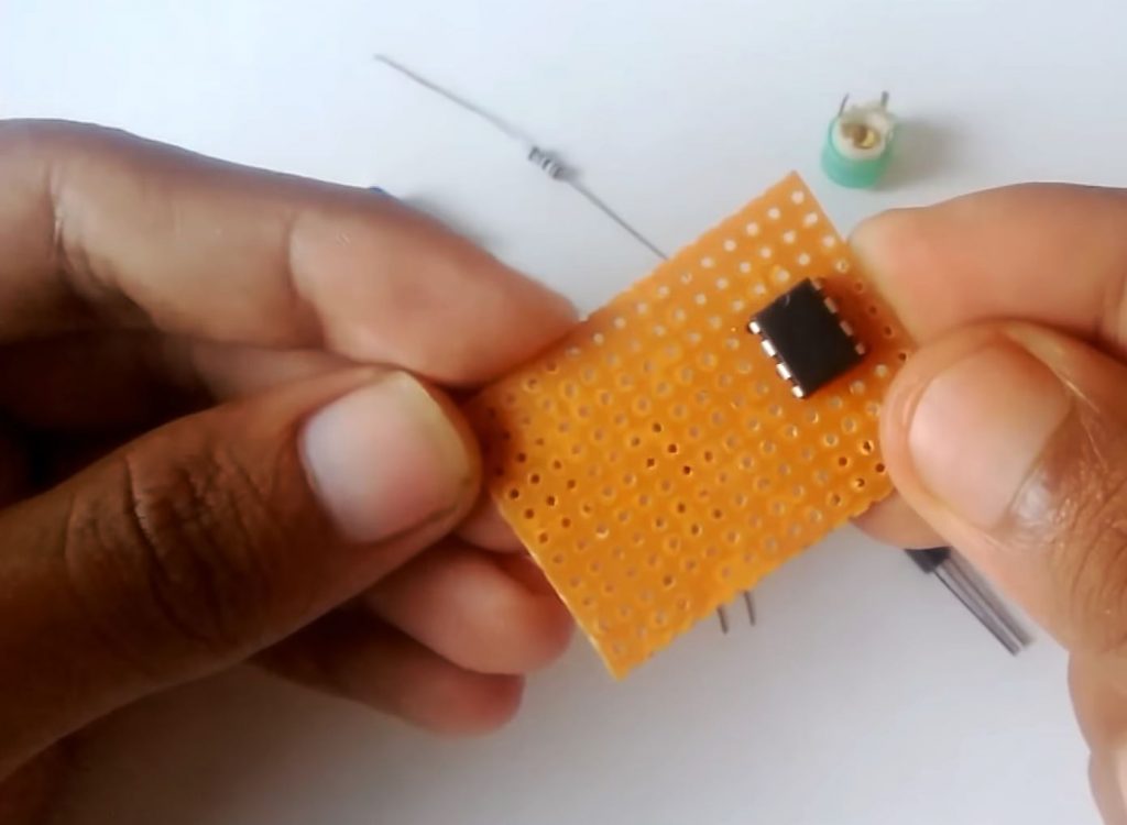
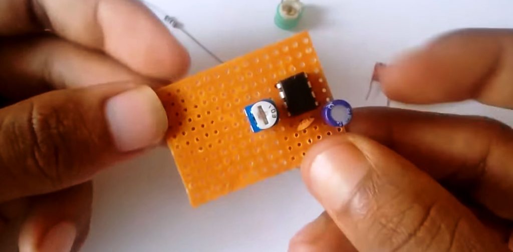
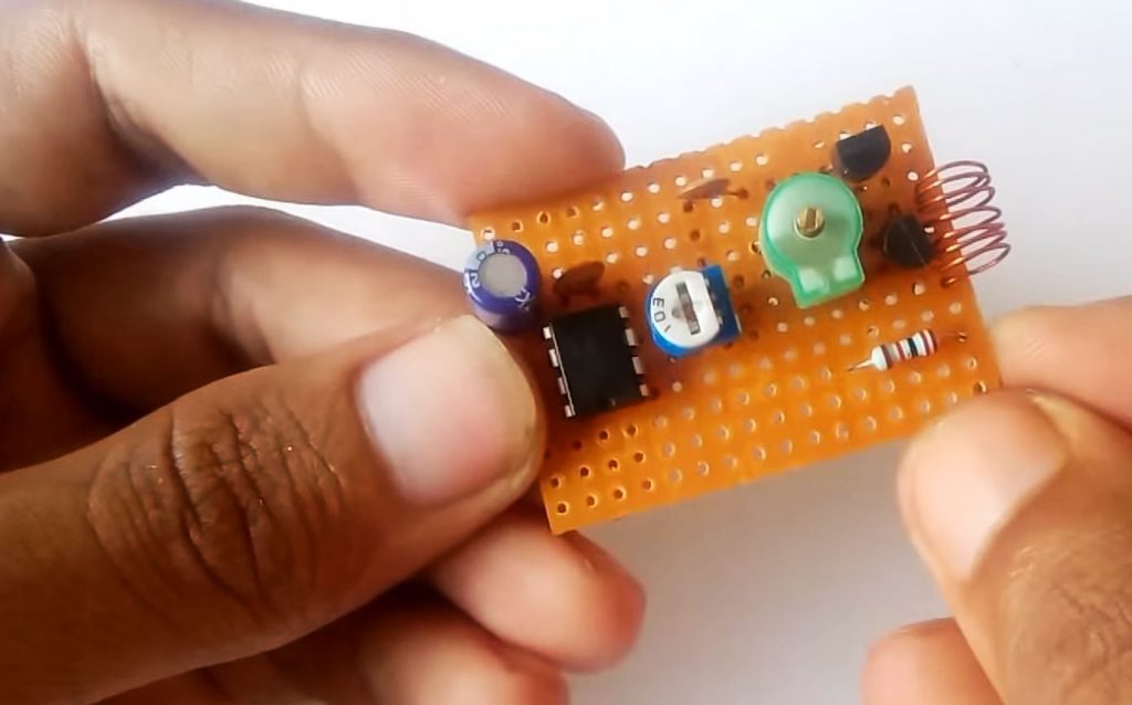
1) Solder the LM386 IC on the veroboard. After that, short pin 2 & 4 of the IC with each other.
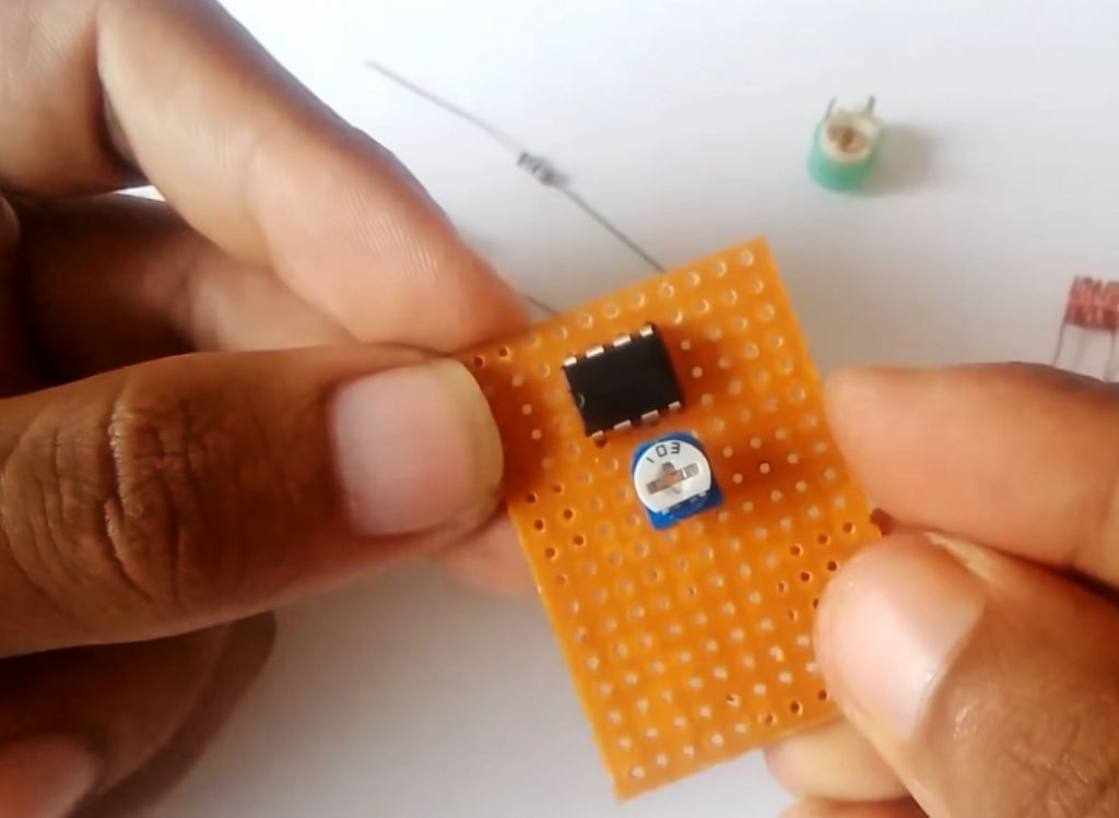
2) After that, Solder the fixed end of the 10K preset pot with pin 2 of the IC and the variable end with pin 3 of the IC.
3) Solder a 100nF capacitor between Pin 4 & 5 of the IC. After that, solder the +ve terminal of the 100uF capacitor with pin 5 of the IC & the -ve terminal to the speakers +ve pin.
4) After that, solder the emitter terminal of the BF494 transistor with pin 2 of the IC. Also. solder a 22pF trimmer capacitor between the collector - base terminal of the trimmer capacitor.
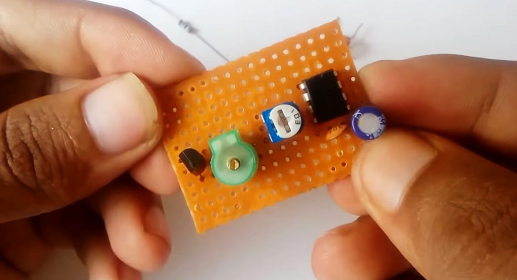
5) Solder the aerial antenna (made by using a 7 Turn Coil of 27 AWG magnet wire) between the collector - base terminal of the BF494 transistor.
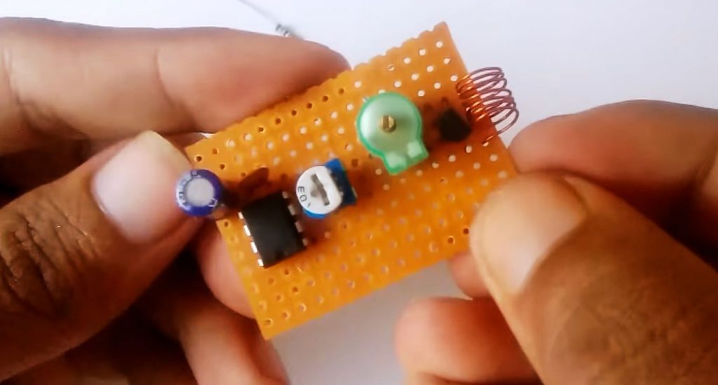
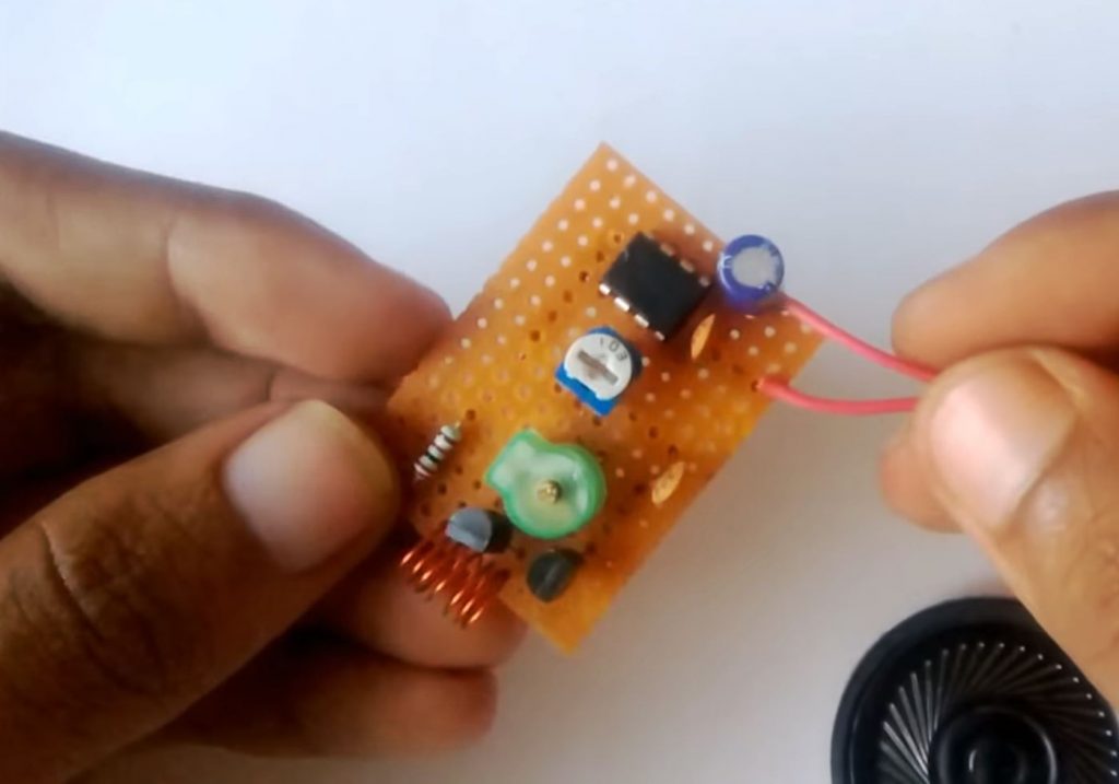
6) After that, Solder the collector terminal of another BF494 transistor with the first transistor's base terminal.
7) Now solder a 100nF capacitor between the base terminal of the second transistor and the fixed end of the 10K preset pot. After that, solder a 22K resistor with pin 6 of the IC, to the collector terminal of the first transistor.
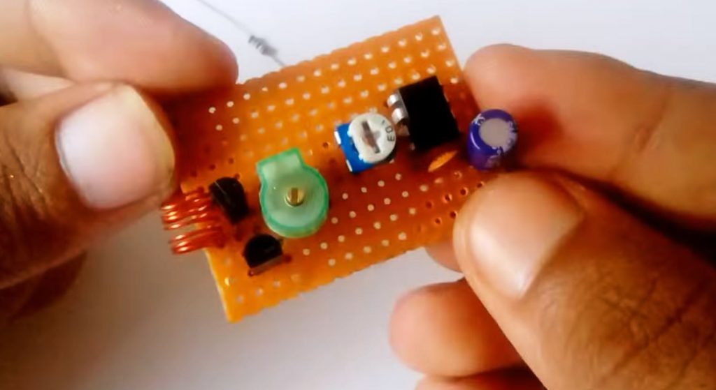
8) After that, solder the +ve & -ve terminal of the 4 Ohms speaker between the -ve terminal of the 100uF capacitor & pin 4 of the IC.
9) Solder the +ve terminal of the battery clip with pin 6 of the IC and the -ve terminal with pin 4 of the IC.
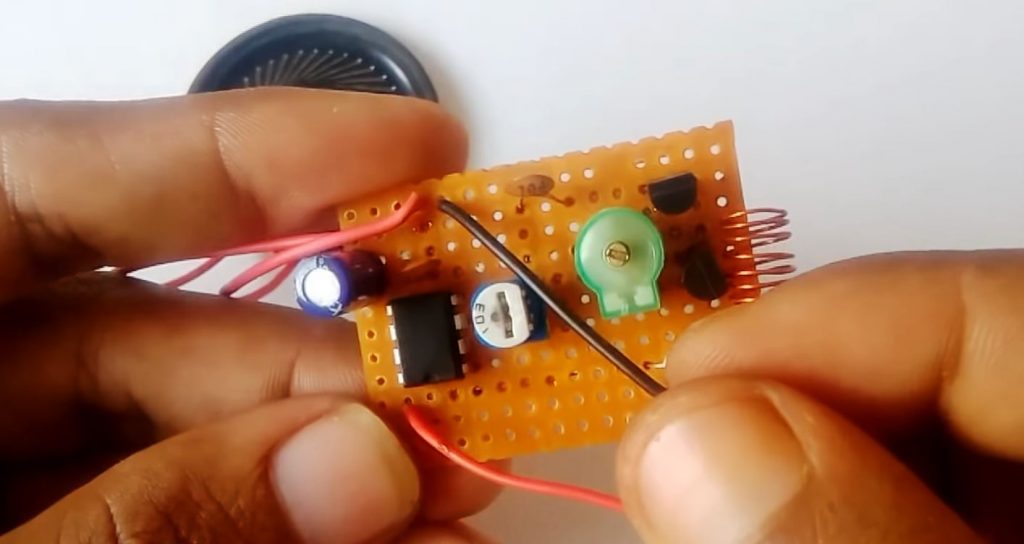
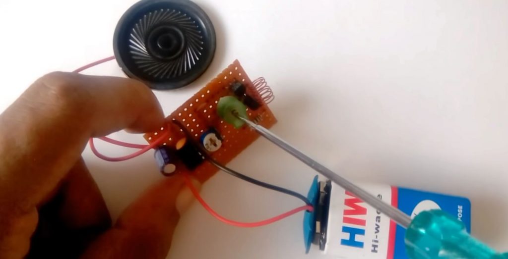
10) Power up & test the circuit.
Circuit Diagram
Working Explanation
This circuit is a simple implementation of an FM radio receiver that can receive local radio reception by utilizing a small no. of components. In the first stage, the modulated signal received by the antenna goes to the tuner circuit through an antenna. Here an LC tank circuit (L1, C1, and the internal capacitances of BF494) sets the frequency desired by the radio receiver. The signal from the tuner output goes to a local Colpitts oscillator. The mixing process is done here, having the received signal as one input and the local oscillator frequency as the other input. The resultant output is a mixture of two frequencies produced by the mixer, which is called the Intermediate Frequency (IF)
[post_start1]The received modulated signal is now demodulated with the same process used at the transmitter side. The frequency discrimination is generally used for FM detection. The output from the demodulator is then sent to the inverting input of the LM386 IC. The amplified output from the IC then passes through some filtering capacitors before it can be taken to an audio transducer such as a loudspeaker. You can tune the trimmer capacitor in order to properly home in on the FM carrier so that you get a clear and crisp output from the speaker.
Applications
- Mostly used in devices such as walkie talkies & ham radios
- Also used in home theatre setups and car radios.
See Also: Ding Dong Sound Generator Circuit | How to setup WiFi on Raspberry Pi 3? | Arduino DC Motor Control using L298N Motor Driver
Comments 0
Be the first to comment.
Leave a comment