

A MOSFET Transistor tester is a simple electronic testing circuit that allows you to test the electrical behavior and operational functionality of transistors, MOSFETs & solid state diodes. It is a pretty useful tool and is usually used by technicians and students alike. It allows the user to be able to detect whether transistor, MOSFET, or diode is operational, But it cannot provide details on the electrical parameters of the device itself. So, in today’s tutorial we are going to go over a step by step process on how To Make A MOSFET Transistor Tester Using NE555 precision Timer IC
555 Timer IC
NE555 is a precision timing circuit is capable of producing accurate time delays or oscillation. A NE555 has three basic modes of operations. In the time delay or mono-stable mode of operation, the timed interval is controlled by a single external resistor and capacitor network. In Bi-stable mode, the output can be configured to latch on a certain voltage level for an indefinite period of time and can be sent back to the zero states by resetting the IC. For an a-stable mode of operation, the frequency and duty cycle can be controlled independently with two external resistors and a single external capacitor.
Here, the NE555 timer IC is configured to operate in astable multivibrator mode, producing a continuous square wave signal. An astable multivibrator is a free-running oscillator that switches continuously between its two unstable states. With no external signal applied, the transistors alternately switch from cutoff to saturation state at a frequency that RC time constants of the coupling circuit determine.

Hardware Components
You will need the following parts to build this project:
| S.No | Component | Value | Qty |
|---|---|---|---|
| 1) | Timer IC | NE555 | 1 |
| 2) | Diode | 1N4007 | 1 |
| 3) | Transistor | BC547 | 1 |
| 4) | Header Pins | Female | 3 |
| 5) | Resistor | 33K, 220 Ohm | 5 |
| 6) | Capacitor | 10uF | 1 |
| 7) | LED | 5mm, 3.5V | 2 |
| 8) | Soldering Iron | 45W – 65W | 1 |
| 9) | Soldering Wire with Flux | – | 1 |
| 10) | DC Battery | 9V | 1 |
| 11) | Battery Clip | – | 1 |
| 12) | Veroboard | – | 1 |
| 13) | Jumper wires | – | As per need |
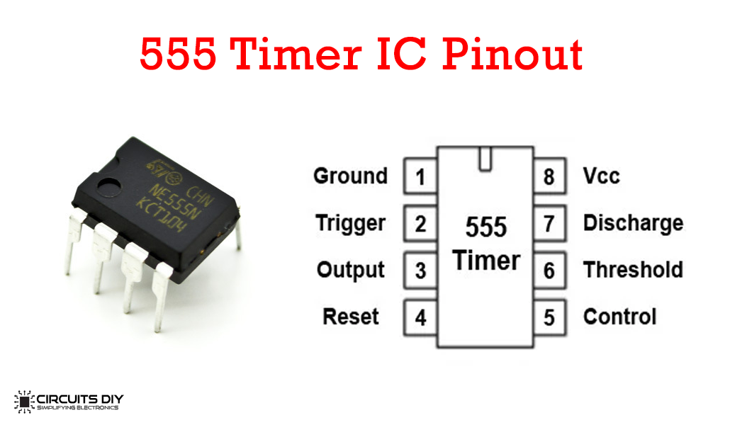
555 Timer Pinout
Useful Steps
1) Solder the NE555 timer IC on the veroboard. After that, short pin 4 & 8 of the IC. Also short pin 2 & 6 of the 555 timer IC.


2) Solder a 33K Ohm resistor between pin 2 & 3 of the IC.

3) Solder the female header pins on the veroboard.

4) After that, solder a 220 Ohm resistor between pin 3 and pin 8 of the IC.

5) Solder the cathode pin of one 1N4007 diode with the anode pin of the other. After that solder one anode – cathode junction with the female header pin (collector) and the other junction with a 220 Ohm resistor.

6) Similarly, Solder the cathode pin of one LED with the anode pin of the other LED. After that solder one anode – cathode junction with the female header pin (emitter) and the other junction with the anode – cathode junction of the 1N4007 diode pair.

7) After that, solder a 220 Ohm resistor between the anode – cathode diode junction and the female header pin (base).

8) After that, solder the +ve pin of the 10uF capacitor with pin 2, 6 of the IC, and -ve pin with the GND of the circuit.

9) After that, solder a 220 Ohm resistor between pin 3 of the IC, emitter female header and the base female header.

10) Solder the battery clip with pin 4 & 8 of the timer IC.

11) Power up the circuit using a 9V battery. After that, tet the circuit using a BC547 transistor.


Working Explanation
The working of this circuit is actually pretty simple. Here, we are using a 555 timer Ic running in astable multivibrator mode, producing a free running square wave depending upon the RC time constant. The tester basically applies a small signal on the base of the testing transistor in order to determine its functionality.
With no transistor connected, the LEDs flash alternatively. If a healthy transistor is connected across the test points. The Green will start to blink. If a faulty transistor (short or dead) is connected across the test points, the test points will remain open and the IC output will bypass through the RED LED, causing it to blink.
Applications
- Usually used for performing functional test of transistors, MOSFETS, diodes, etc.
- Also used in semiconductor design to determine operation of the product during final testing.
See Also: H Bridge Motor Controller Using Power Transistors | How To Make An Audio Power Amplifier Using TDA2003 Amplifier IC | Touchless Hand Sanitizer Dispenser Using Servo Motor And 555 Timer IC

