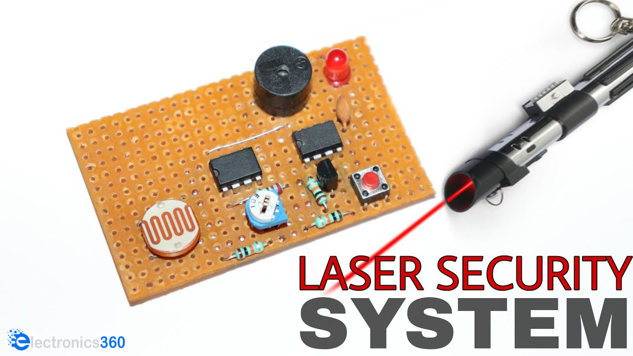
How To Make A Laser Tripwire Home Security System Using 555 Timer IC
What is a Laser Tripwire Home Security System?
Home security setups allow you to protect your private property from any undesirable intrusion of burglars and robbers. They have become a necessity in such uncertain times and no home is truly safe without the presence of at least some semblance of home security setup. A laser tripwire security system raises an alarm when breaks its line of sight. They are commonly used in places such as bank vaults & museums, in order to protect high value objects from thieves. So, in today's tutorial, we are going to go over a step by step procedure on How To Make A Laser Tripwire Home Security System Using 555 Timer IC, an amplifier, and an LDR.
[post_start1]The heart of this laser security system is a light dependent resistor or an LDR. LDRs are electronic components that are sensitive to light intensity. Its behavior is similar to a photocell that works on the principle of photoconductivity. The resistance value of an LDR decreases when the intensity of light increases. The threshold voltage of the NE555 timer IC is decided by the output voltage of the voltage divider configuration (LDR & R2), here the NE555 is running in astable (free running mode).
Hardware Component
You will need the following parts to build this project:
| S.No | Component | Value | Qty |
|---|---|---|---|
| 1) | Timer IC | NE555 | 1 |
| 2) | Op-Amp | LM358 | 1 |
| 3) | LDR | 5mm | 1 |
| 4) | Buzzer | 5V | 1 |
| 5) | NPN Transistor | BC547 | 1 |
| 6) | Potentiometer | 10K | 1 |
| 7) | Pushbutton | - | 1 |
| 8) | Capacitors | 100nF | 1 |
| 9) | Resistor | 10K, 220Ohm | 4 |
| 10) | Soldering Iron | 45W - 65W | 1 |
| 11) | Soldering Wire with Flux | - | 1 |
| 12) | Veroboard | - | 1 |
| 13) | DC Battery | 9V | 1 |
| 14) | Battery Clips | - | 1 |
| 15) | Jumper Wires | - | As per need |
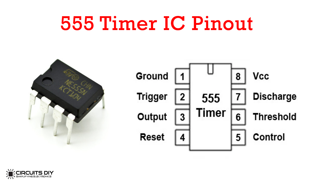
555 Timer Pinout
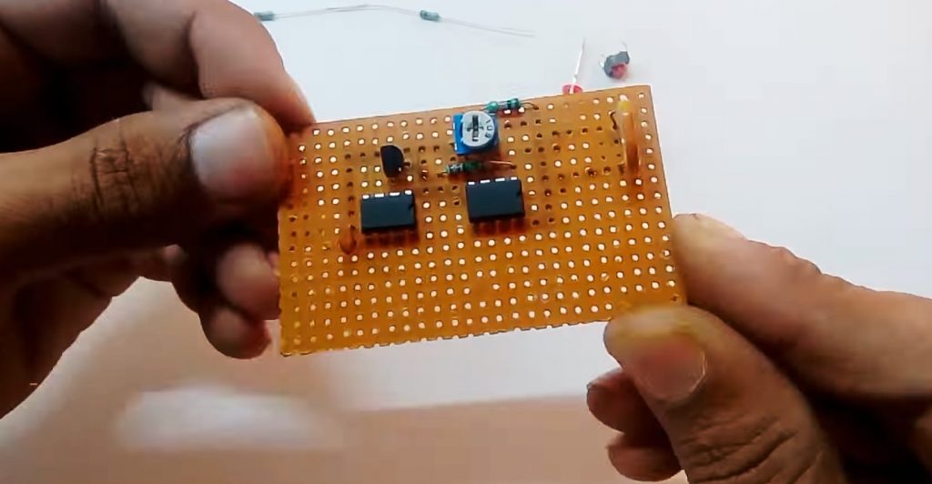
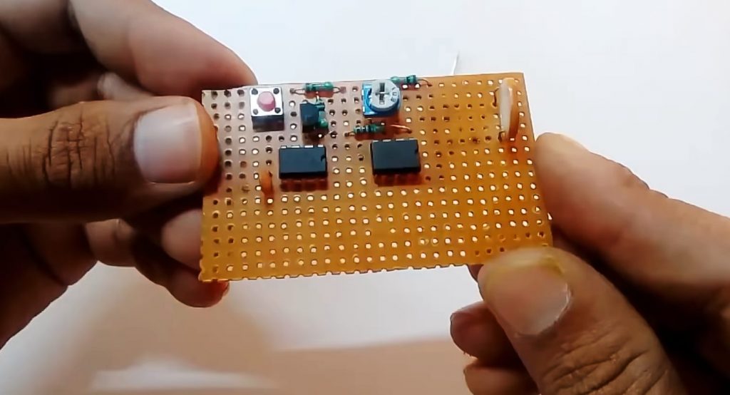
Useful Steps
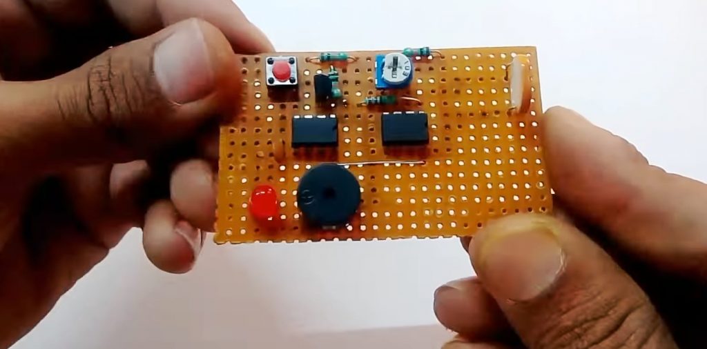
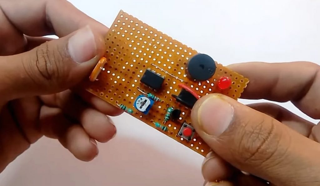
1) Solder the NE555 timer IC & the LM358 Op-Amp on the veroboard.

2) After that solder the fixed ends of a 10K pot on pin 4 & pin 8 of the timer IC. Also, solder the middle pin of the 10K pot with pin 2 of the LM358 IC.

3) Now solder a 10K resistor between pin 3 & pin 8 of the Op-amp IC. After that, Solder the LDR between pin 3 & pin 4 of the LM358 IC.

4) After that, solder the collector terminal of the BC547 transistor with pin 2 & the emitter terminal with pin 1 of the 555 timer IC.

5) Solder a 220Ohm resistor between the output pin of the LM358 Op-Amp & the base pin of the BC547 transistor.

6) After that, Solder a 100nF capacitor between pin no.5 and 1 of the timer IC.
7) Solder a Reset pushbutton between pin 4 & pin 1 of the 555 timer IC.

8) After that solder a 10K resistor between pin 4 & 8 of the timer IC. Also, solder another 10K resistor between the collector terminal of the BC547 transistor and pin 8 of the 555 timer.
9) Solder the -ve pin of the LED and the Buzzer with pin 1 of the 555 timer & the +ve terminal with pin 3 od the 55 timer iC.
10) Sodler the +ve terminla of the battery clip with pin 8 of the IC & -ve with pin 1 of the IC.
11) Power up and test the circuit using a 9V Battery.

Circuit Diagram
Working Explanation
The working of this laser home security system is as follows. when the line of sight between the LDR & the laser diode breaks, the light intensity over the LDR decreases. This increases the resistance of the LDR & sends a control input to inverting input pin of the LM358 Op-Amp.
[post_start1]The amplifier output then serves as a control signal to the base of the BC547 transistor. the collector output from the transistor serves as the triggering input for the 555 timer IC. Here, the IC is running in Bi-stable multivibrator mode, meaning that the output of the IC will latch to a constant high until the IC is reset. The output from the IC then 5V buzzer, indicating the presence of an intruder in the vicinity.
Applications
- Laser security alarms are used in places such as residential, commercial, industrial, and military properties for protection against theft or property damage.
See Also: Ding Dong Sound Generator Circuit | LC Meter Circuit using 555 Timer | Bike Turning Signal Circuit
Comments 0
Be the first to comment.
Leave a comment