Fire Alarm Circuit Using NTC Thermistor and BC547 Transistor
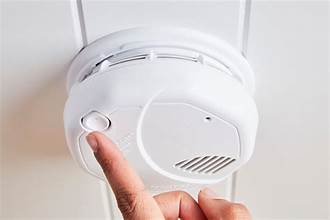
A fire alarm is one of the best beginner projects for understanding how a sensor, a bias network and a transistor switch work together. This circuit uses a 10k NTC thermistor as the heat sensor and a single BC547 transistor as the switch. There is no microcontroller and no special IC — just a handful of parts and a 9V battery.
When the temperature near the thermistor rises sharply, the alarm load (a buzzer or small siren) switches on along with a red LED indicator. A preset lets you set the temperature at which it triggers.
Circuit Diagram
The editable version of this schematic is saved in the Circuit Design app as “Fire Alarm Circuit (NTC Thermistor + BC547)”, so you can open it, run the rules check and modify values directly.
Components Required
- BT1 — 9V battery with clip
- SW1 — SPST ON/OFF switch
- TH1 — 10k NTC thermistor
- RV1 — 1k preset / trimpot
- R1 — 1kΩ resistor (base)
- R2 — 470Ω resistor (LED series)
- Q1 — BC547 NPN transistor
- D1 — 5mm red LED
- LA1 — 9V active buzzer or small siren
- Breadboard or perfboard and hookup wire
How the Circuit Works
An NTC thermistor has a negative temperature coefficient: its resistance falls as it gets hotter. A typical 10k NTC measures about 10kΩ at 25°C and drops to roughly 2–3kΩ when heated to 60–70°C.
- The sensing divider. TH1 sits between the +9V rail and the base node, and RV1 runs from that node down to 0V. The node voltage is 9V × RV1 ÷ (TH1 + RV1).
- At room temperature. With TH1 near 10kΩ and RV1 set to about 600Ω, the node sits near 0.5V — below the 0.65V a silicon transistor needs to start conducting. Q1 stays off and the alarm is silent.
- When heat arrives. TH1 falls to a couple of kΩ, the node climbs past 2V, and current flows into the base through R1.
- The switch. R1 limits base current to roughly 1.4mA. With a typical BC547 gain of 200 or more, the transistor saturates easily and pulls the collector down to about 0.2V.
- The output. LA1 (the buzzer or siren) is connected between the +9V rail and the collector, so it now has almost the full supply across it and sounds. R2 and D1 sit in parallel with it and give a visual indication at about 14mA.
Setting the Trip Point
- Power up the circuit at normal room temperature.
- Turn RV1 slowly until the buzzer just starts to sound, then back it off until it goes quiet again.
- Back it off a little further to leave headroom — otherwise a warm afternoon will set it off.
- Test by holding a soldering iron or a lighter flame near the thermistor (never touching it). The alarm should sound within a few seconds, and stop once TH1 cools.
If the alarm triggers too easily, reduce RV1. If it never triggers even with strong heat, increase RV1 slightly, and check that TH1 really is an NTC type and not a PTC.
Design Notes and Improvements
- Use an active buzzer. It produces a tone from DC and needs no oscillator. If you use an electromagnetic buzzer or a relay, add a 1N4007 across it (cathode to +9V) to absorb the switch-off spike.
- Keep the sensor on leads. Mount TH1 on a short twisted pair so it can sit where heat collects, near the ceiling, while the board stays elsewhere.
- Add a latch. As drawn, the alarm stops once things cool down. A small SCR or a second transistor cross-coupled as a latch keeps it sounding until you reset power.
- Sharper triggering. Replacing the transistor stage with an LM393 comparator gives a crisper, more repeatable threshold and adds hysteresis.
- Detect smoke too. Heat alone is a late indicator. An MQ-2 gas/smoke sensor or a proper photoelectric module reacts far sooner.
Important Safety Note
This is a learning and demonstration project. It is not a replacement for a certified smoke alarm. A heat-only sensor responds only when a fire is already well developed and close by, and it has no self-test, no low-battery warning and no third-party certification. Keep proper certified smoke alarms installed in your home and treat this circuit as a bench project.
Summary
With nine components you get a working heat-activated alarm that demonstrates voltage dividers, thermistor behaviour, transistor biasing and switching a load. It builds on a breadboard in a few minutes, and it is an ideal base for experimenting with latching, comparators and smoke sensing.
Comments 1
Hi this is such an informative post. Thanks for sharing this content
Leave a comment